Googling the terms ‘3D scanning’ and ‘reverse engineering’ will very quickly see you inundated with offers to get you from ‘scan to CAD’ in the fastest, easiest way possible.
With 3D modeling now vital to product design, a considerable amount of hype has built up around technologies that generate CAD data from existing objects. However, we’re talking about reverse engineering here – an often complex process of uncovering design intent.
So just how easy is it to go from scan to CAD in reality? If you’re completely new to reverse engineering, don’t worry! We’ll start by covering the basic concept, before outlining a general workflow, and giving you tips on how to achieve reliable, professional results.
What is reverse engineering?
In essence, reverse engineering is the process of uncovering the design of a physical product – usually to gain a better understanding of how it works. This information is vital to repairing faulty products or recreating those that can no longer be sourced.
3D scanning may not be the only way to reverse engineer something, but it is more efficient than manually taking it apart and measuring with calipers, or capturing with traditional CMM machinery. Not only is 3D scanning non-contact, it’s ultra-fast, in a way that makes it ideal for digitizing old product designs and using resulting models as a basis for iteration.
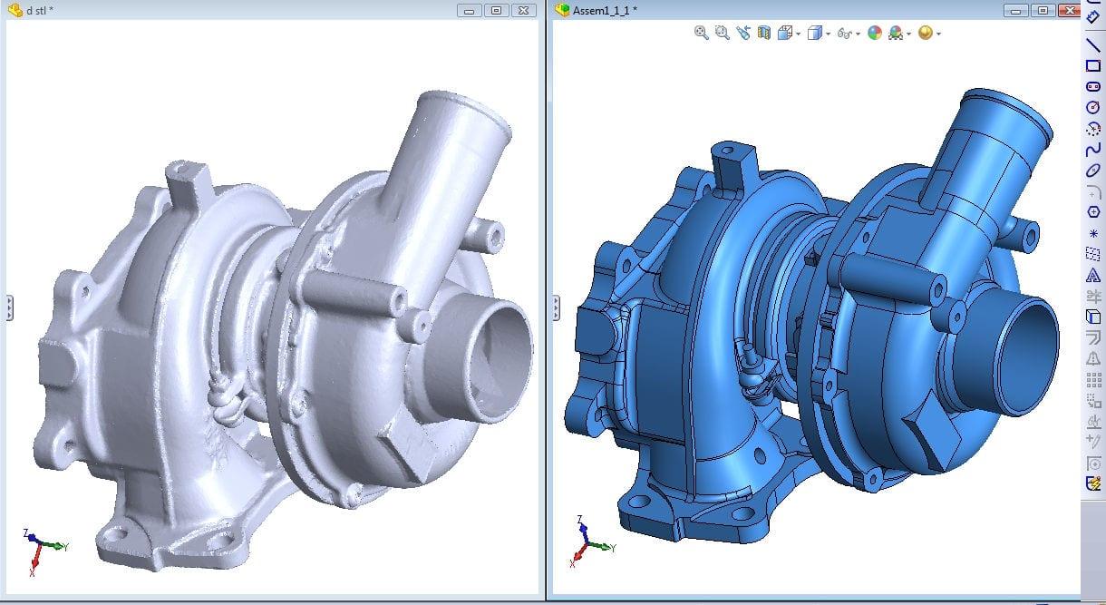
However, you generally can’t just use 3D mesh data in product design. You need to convert this into usable CAD data first – and it’s this process that’s known as scan to CAD. At a glance, the workflow itself is relatively straightforward: simply scan, optimize your mesh, convert to CAD, and make any modifications – seems easy enough, right?
Well, achieving high accuracy and repeatability can be more difficult than it sounds. Let’s take a look at the core workflow steps and what you can do to ensure products meet requirements.
Scan to CAD: A basic guide
Step 1: Data capture
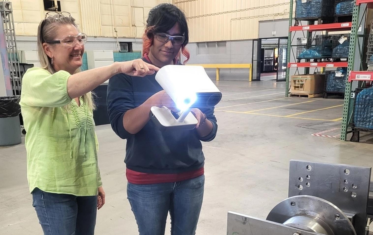
The first step is 3D scanning whatever you intend to reverse engineer. Whether you can achieve this with ease, speed, and accuracy, will depend on which 3D scanner you choose.
If you’re new to the technology, wireless devices with built-in displays are the easiest to pick up and use. They’ll give you real-time feedback, helping ensure complete data capture, and won’t hamper your efforts with cables. Generally, you shouldn’t require targets for submillimeter accuracy. But those reverse engineering parts with tolerances of just a few microns will need them.
For best results, you’ll need to capture absolutely all the critical features of your product. Missing surface data won’t make it into your final 3D model. So try to be thorough!

Step 2: Mesh optimization
After 3D scanning, you’ll be left with a cloud of captured points. Most leading scanner manufacturers offer a dedicated software for turning these into editable 3D meshes.
This process involves registering, aligning, and fusing data. Once you’ve removed unwanted points or ‘outliers,’ it’s important to fill any holes. It’s also advisable to reduce mesh polycount – this will make it easier to work with third-party software later.
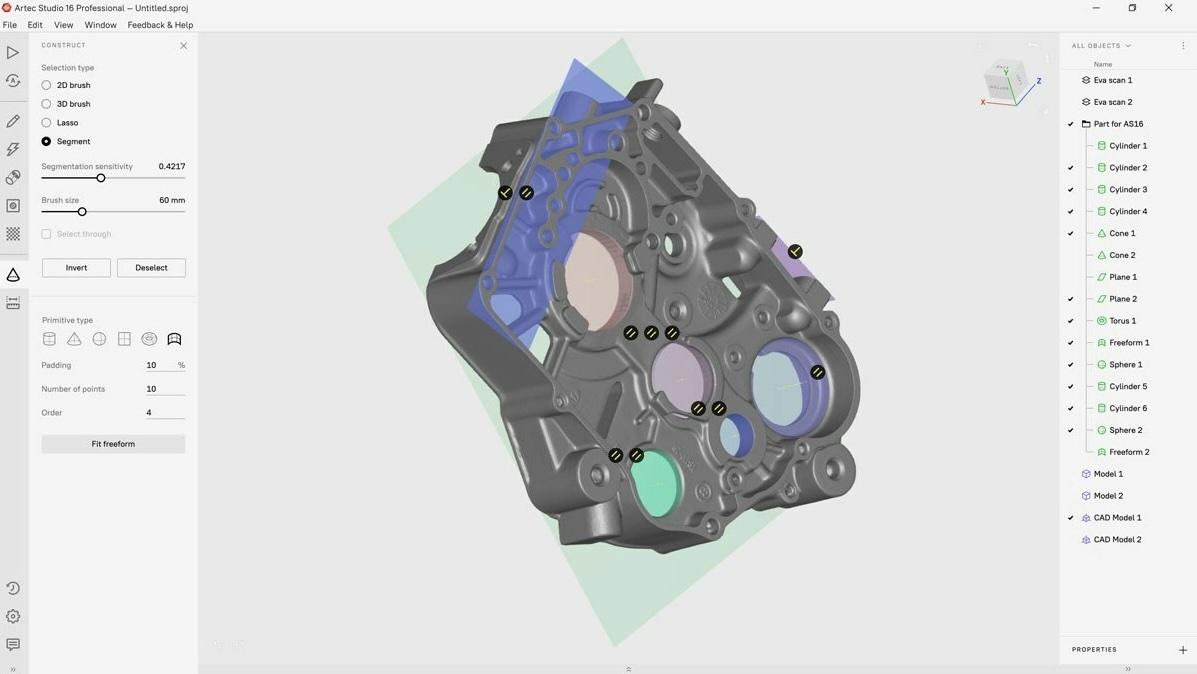
Your scan data capture and processing program may even come with essential mesh editing and CAD generation tools. Often, these allow you to add chamfers and fillets, fit primitives, and auto-generate surfaces from curved designs. But industrial reverse engineering can require more advanced toolkits, provided by the likes of Design X and SOLIDWORKS.
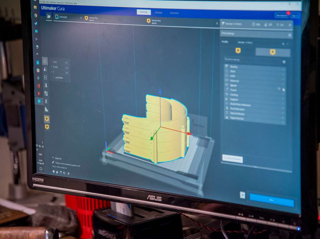
On the other hand, if you plan on 3D printing your model, files can sometimes be exported directly as STLs for slicing – it depends on your project needs.
Step 3: Generate CAD bodies
Turning imported data into solid, feature-based CAD bodies is the most vital and skill-intensive step in the entire process. That said, there are several ways to achieve this goal.
Again, you can convert from STL meshes to CAD with auto-surfacing. This is the easiest way to generate CAD data, but it’s not parametric and therefore of limited use in manufacturing. For more advanced reverse engineering, it’s best to manually sketch part geometries, so you get all the critical dimensions right – and this can be vital to understanding design intent.
For example, if you identify that your product needs to be a certain thickness, you can uncover defects like warping and ensure that it meets requirements. Manual reverse engineering also delivers peak accuracy, which is ultimately the key to perfecting the process.
Then there’s hybrid reverse engineering, which involves dividing parts into regions, extracting shapes, and making extrusions or intersections between solid bodies. Like auto-surfacing and sketching it requires legwork, but the results are impressive: true-to-life CAD models.
Step 4: Deploy your 3D model
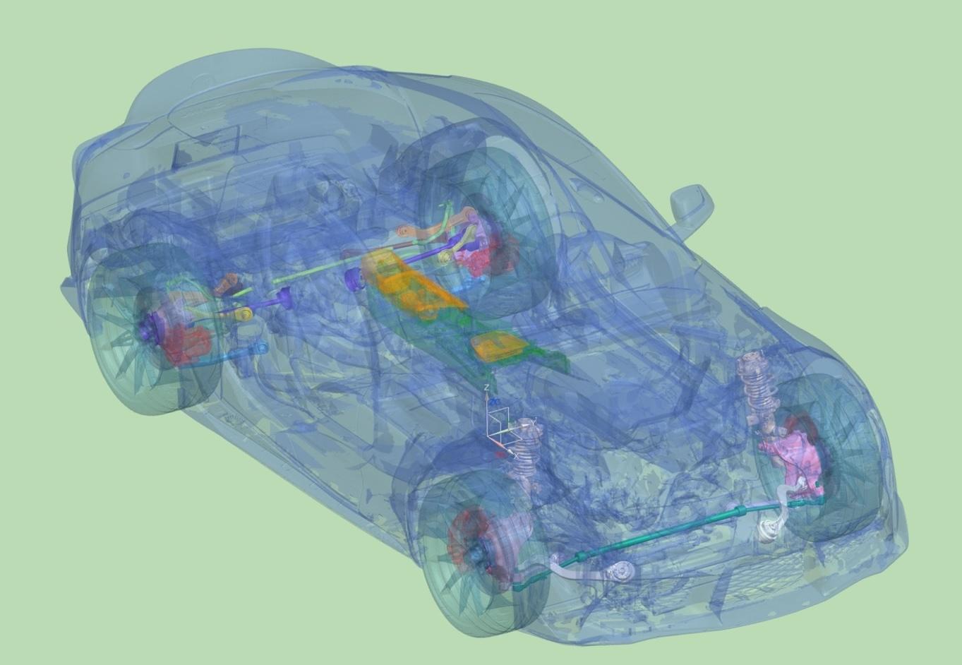
CAD design really has taken over – wherever products need to be designed and enhanced, the technology is indispensable. Scan-based CAD data can be fed into simulations, for instance, to discover how parts will perform in reality. It can also be sent to another design platform for iteration or exported straight to MES software for manufacture. The choice is yours.
Best scan to CAD software in 2025
If that all sounded daunting, don’t worry. There are plenty of products out there to help you through the reverse engineering workflow. At stages one and two, you’ll need an intuitive scanner and software duo – and here you can’t go wrong with Artec Studio.
Designed to work with a wide range of 3D scanners, and capable of everything from microscale reverse engineering to facility digitization, the software is so straightforward that it takes mere hours to master. Its autopilot feature also automates many processing steps, while leaving the door open for advanced users to manually polish meshes themselves.
Other scanner manufacturers have dedicated offerings too. Open-source platforms like MeshLab have their own merits, but these don’t cover all bases in quite the same way.
When it comes to the business end of reverse engineering: generating CAD bodies, Fusion 360, QuickSurface, CATIA, and ZEISS Reverse Engineering all offer industry-favorite features. Users tend to choose between them based on cost, capability, and usability. Fusion360 may be more accessible than CATIA, for instance, but it’s less advanced so not as popular in industry.
So it really does depend on your application. High complexity and fine tolerances may require the industry’s best. However, this could be overkill for reverse engineering basic geometries, where open source or freemium model platforms may suffice.
Scan to CAD: Easier than ever?
Returning to our initial question: How tricky is it to go from scan to CAD? We say the proof is in the pudding. The process is already being used around the world, to rapidly create spare parts no longer in production, analyze products in-depth, and improve upon existing designs.
Achieving best results still requires some operator skill, but many early workflow steps can be automated, and the industry continues to figure out ways of making life easier for users. In short, if you’re considering getting into reverse engineering, now is a great time. There’s plenty of support out there and the journey from scan to CAD is only getting smoother!
